
Correct cable tray sizing is one of the most critical steps in electrical system design. Many project failures, such as cable overheating, reduced ampacity, difficult maintenance, and on-site reconstruction, stem from improper tray dimension selection — either overloaded cable capacity or insufficient heat dissipation space. Complying with IEC 61537 and NEC Article 392 international standards, this guide systematically explains how to calculate cable tray size based on actual cable quantity, cross-sectional area, and thermal dissipation requirements, helping electrical engineers and contractors achieve safe, compliant, and cost-effective cable capacity layout design.
Why Scientific Tray Sizing Matters (Capacity & Heat Dissipation)
Cable trays are not merely structural supports for cables. Their internal space directly determines two core performance indicators: cable accommodation capacity and heat dissipation efficiency.
Excessively small trays lead to dense cable stacking, blocked air circulation, and accumulated operating heat. This continuously reduces cable current-carrying capacity, accelerates insulation aging, and even triggers short-circuit risks. Conversely, oversized trays cause unnecessary cost waste and space redundancy. Reasonable sizing balances full cable utilization, stable thermal dissipation, code compliance, and future expandability.
Core Standard Fill Ratios (IEC 61537 & NEC 392 Rules)
Cable Tray's Fill ratio refers to the percentage of total cable cross-sectional area occupying the tray’s internal usable area. It is the core basis for size calculation and heat dissipation control, with unified authoritative standards for global engineering projects.
•Single-layer cable laying (power/control cables): Maximum fill ratio ≤ 50%
Reserve half of the space for natural air convection to ensure basic cable tray heat dissipation during long-term operation.
•Multi-layer stacked cable laying: Maximum fill ratio ≤ 40%
Stacked cables easily form heat accumulation in the core layer; the stricter 40% standard effectively avoids thermal overload and ampacity derating.
•Instrument & low-voltage signal cables: Allowable fill ratio ≤ 50%
Low power consumption and low heat generation, meeting basic layout and heat dissipation requirements.
Key reminder: The fill ratio limit is a safety threshold rather than a design target. Sufficient margin must be reserved for high-temperature environments and long-term continuous operation scenarios.
Step-by-Step Cable Tray Size Calculation Method
Step 1: Count all cables and calculate total cross-sectional area
Sort all cables to be laid in the tray, record the outer diameter of each cable (including insulation and outer sheath), and calculate the individual cable cross-sectional area. Sum all areas to obtain the total cable CSA (cross-sectional area).
Formula: Cable Area = π × (Cable Outer Diameter/2)²
Step 2: Determine the minimum required internal area of the tray
According to the most commonly used multi-layer laying standard (40% fill ratio for universal projects), calculate the minimum tray area to meet capacity and heat dissipation requirements:
Minimum Tray Internal Area = Total Cable CSA ÷ 0.4
For single-layer neat laying with low heat generation, the 50% fill ratio can be adopted appropriately to optimize space utilization.
Step 3: Match standard tray width and depth specifications
Calculate the required internal area and select the closest standard cable tray size. Common conventional widths include 100mm, 200mm, 300mm, 400mm, 600mm, and depths include 50mm, 100mm, 150mm. Always round up the specification instead of choosing a smaller size to avoid overloading.
Step 4: Reserve expansion margin
For long-term industrial and municipal projects, it is recommended to reserve 10%–20% redundant space for later cable replacement, circuit upgrading, and new circuit addition, preventing secondary reconstruction caused by insufficient tray space.
Key Factors Affecting Heat Dissipation & Sizing Accuracy
1. Cable Tray Structure Type
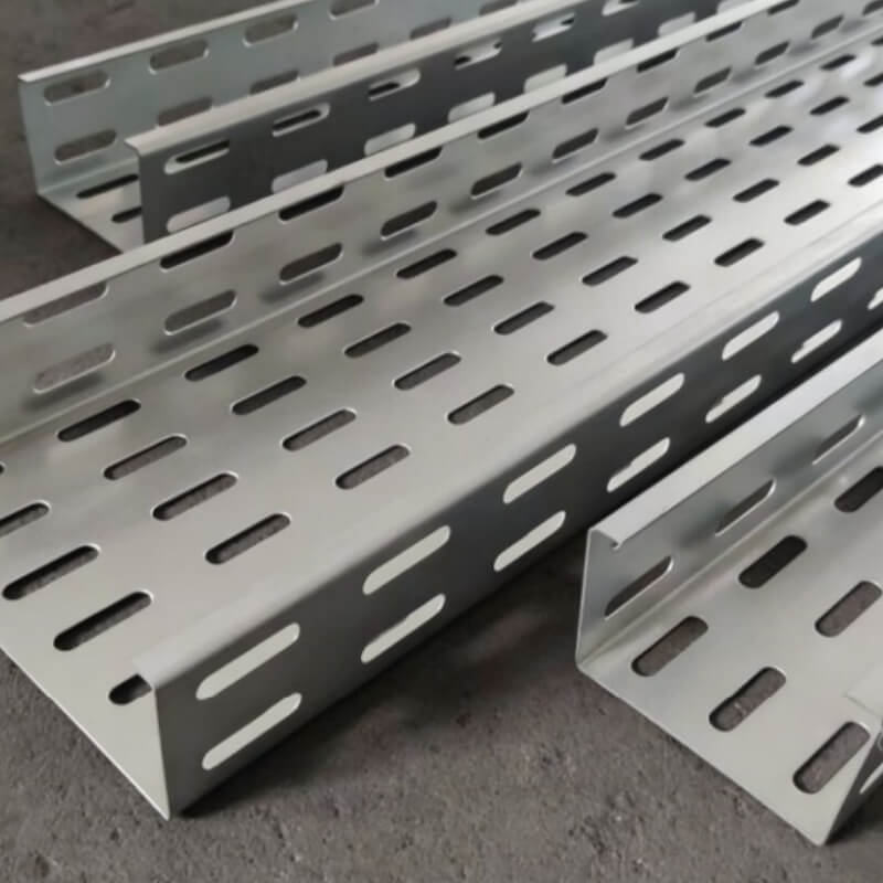
Ventilated and open-structured trays (perforated cable tray, cable ladder) have superior air circulation and heat dissipation performance, suitable for high-power cable laying. Solid-bottom cable trays have relatively poor heat dissipation and require stricter fill ratio control to avoid heat accumulation.
2. Ambient Temperature & Installation Environment
For high-temperature workshops, closed pipe corridors, and poorly ventilated spaces, the fill ratio should be appropriately reduced (controlled below 35%–40%) to enhance natural heat dissipation and ensure stable cable operating temperature.
3. Mixed Laying of Power & Signal Cables
Mixed wiring will cause superposition of heat and electromagnetic interference. It is recommended to use separated trays or partition isolation, and appropriately reduce the laying density to balance heat dissipation and signal stability.
Common Sizing Mistakes to Avoid
•Adopting a 50% fill ratio for multi-layer stacked cables, resulting in hidden heat accumulation dangers.
•Only calculating cable quantity while ignoring outer sheath thickness, leading to actual overloading.
•Excessively pursuing space utilization without reserving heat dissipation gaps and future expansion space.
•Uniform sizing for all scenarios without distinguishing ventilation differences between ladder, perforated, and solid trays.
Winwin Standard Cable Tray Solutions
Winwin provides full-standard cable tray series including perforated cable trays, cable ladders, solid-bottom trays, and wire mesh cable trays. All products comply with IEC 61537 and NEMA standards, and are certified by UL/cUL, CE, SGS, and ISO. We support customized width, depth, and thickness specifications, as well as multiple surface treatments (pre-galvanized, HDG, ZAM, stainless steel,powder coated, fire resistance). And we can provide full range cable tray accessories and fittings.
Published by Fujian Winwin Group | UL/cUL & NEMA Certified Cable Tray Manufacturer
Core Keywords
cable tray size calculation, cable tray fill ratio, IEC 61537 cable tray, cable tray heat dissipation, cable capacity layout, NEC 392 cable tray standard, industrial cable tray sizing guide


 Send Email
 WhatsApp