
Drainage Channel System Installation Instructions
Compliant with EN 1433 Standard | For A15–F900 Load Class Projects
Drainage channel systems shall be sorted by load class before installation, and installed properly in line with their matching factory-supplied gratings.
Section I – Trench Excavation
Prior to installation, confirm the finished elevation for the drainage channel.
The dimensions of the foundation trench and reinforced concrete shoulders on both sides of the channel directly determine the overall load-bearing performance.
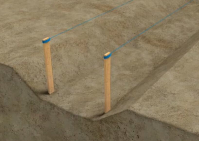
Locate and mark the trench’s central axis aligned with the centerline of the drainage channel before commencing excavation work.
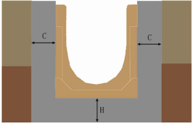
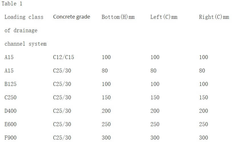
The required reserved clearance dimensions are listed in Table 1 below.
Section II – Foundation Bed Casting
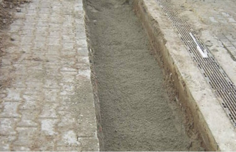
Cast concrete for the channel base in compliance with the load classes specified in Table 1.

Section III – Drainage Channel Installation
Mark out the centerline, set alignment strings and carry out installation sequentially.
If the pre-cast foundation bed concrete has fully cured, prepare semi-dry mortar and lay it underneath the channel base. This creates a seamless bond between the channel body and the trench base concrete.
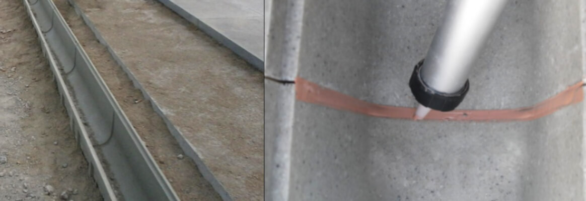
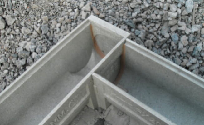
Next, clean the tongue-and-groove joints of the drainage channels. Align adjacent sections tightly, then apply structural sealant to all tongue-and-groove joints to achieve a fully watertight connection.
Section V – Grating Installation
Clear all debris inside the drainage channel before fitting gratings.
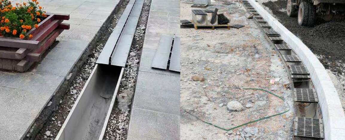
Prior to backfilling concrete, place the matching gratings onto the channel first. The gratings act as lateral supports to prevent deformation of the polymer concrete channel or PP trench channel or Plastic drainage channel walls under concrete lateral pressure. This avoids grating misalignment, jamming or unsightly uneven finishing caused by channel distortion after pouring.
Section VI – Catch Basin & Inspection Chamber Installation
Catch basins are critical accessories for drainage channel systems and have extensive application scenarios.
1. For excessively long channel runs, install a catch basin or Sump pit at mid-span to form a direct connection to municipal sewer pipelines.
2. Fit one catch basin every 10 to 20 meters, equipped with a removable inspection cover. When blockages occur inside the channel, open the inspection cover for quick clearing and maintenance.
3. Insert a stainless steel debris basket inside each catch basin. Regularly lift out the basket to remove accumulated waste and maintain unobstructed channel flow.
VI. Concrete Pouring on Both Sides of Drainage Channel
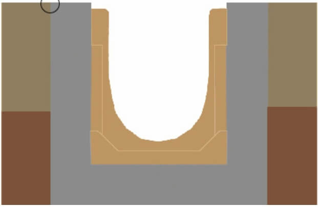
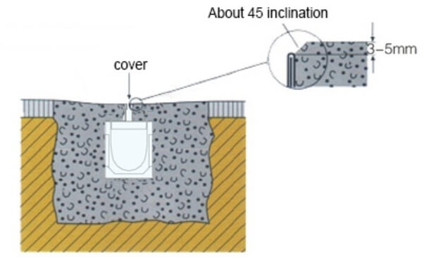
Before pouring concrete on both sides of the drainage channel, fully protect the installed gratings to prevent cement residue from clogging the grating drainage holes or falling into the channel interior. Depending on the required load-bearing capacity, reinforcement mesh may be laid on both sides of the channel before concrete pouring to enhance overall structural strength. The concrete pouring height shall not exceed the pre-defined design elevation.
VII. Pavement Construction
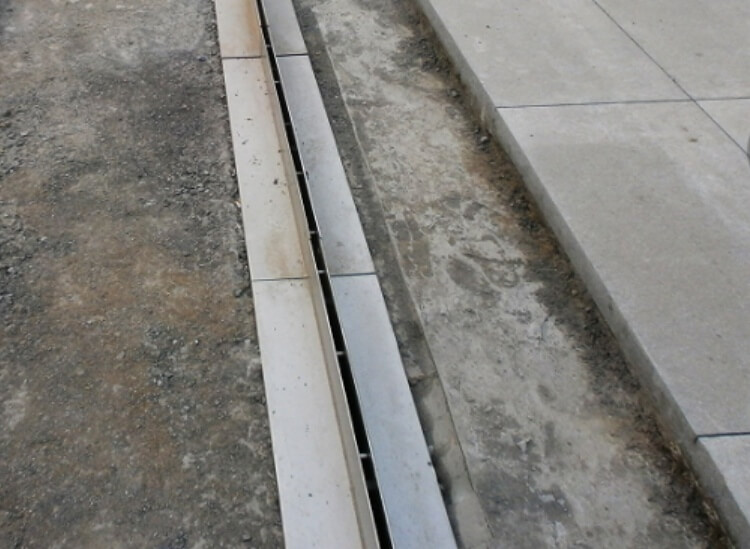
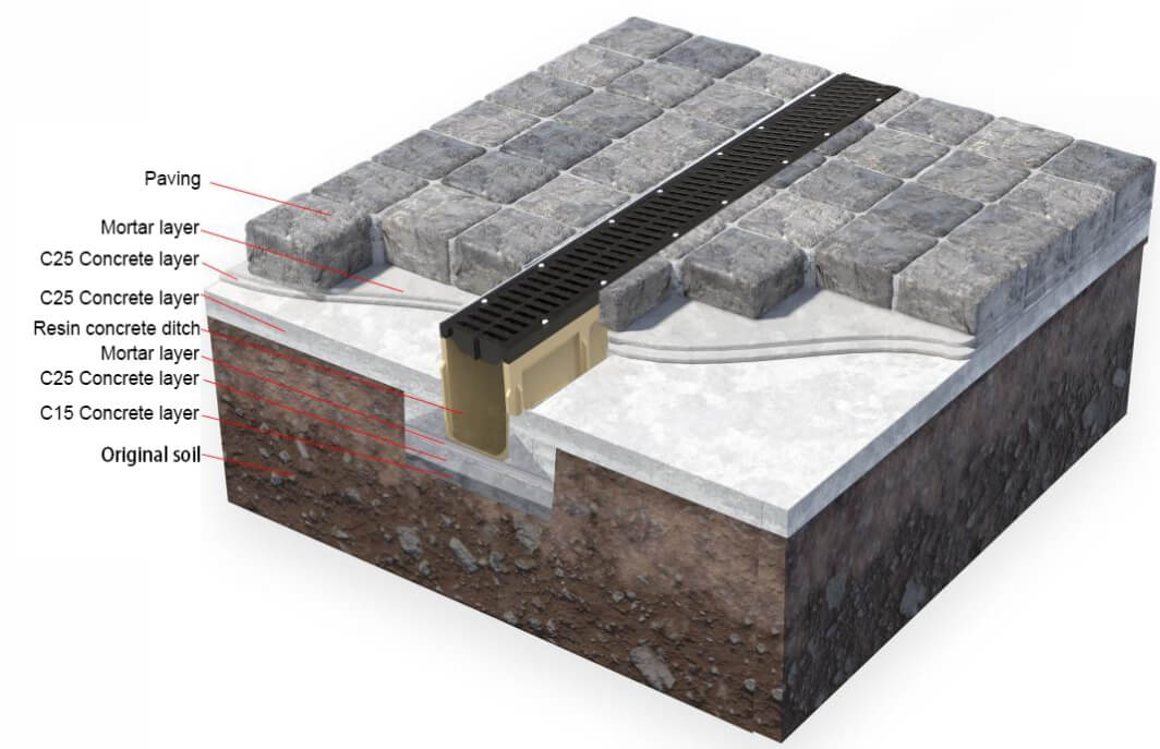
Pavement installation is determined according to the actual site conditions. If pavement works are required, the paving stones shall be installed 2–3 mm higher than the grating surface to ensure smooth water drainage. Adequate cement mortar thickness must be reserved beneath the pavement to prevent loosening and settlement. The pavement shall be laid neatly and closely against the drainage channel to guarantee overall construction quality and a uniform aesthetic finish.
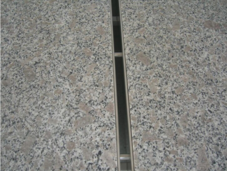
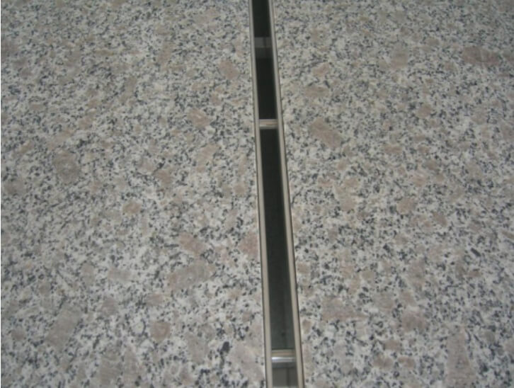
(Effect of slot cover)
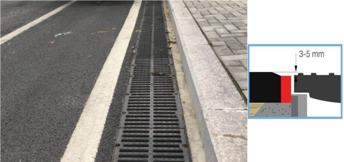
(Effect of ductile iron grating cover)
VIII. Inspection and Cleaning of Drainage Channel System
Upon completion of the entire drainage channel installation, a full on-site inspection and thorough cleaning shall be performed.
Check and remove all residual debris inside the channel. Verify that all inspection covers open and close smoothly, and ensure the catch basins are free of blockages. Inspect all screw-fixed gratings to confirm they are securely fastened without looseness.
The drainage system can only be officially put into service after all inspection items meet standard requirements.


 Send Email
 WhatsApp